Modeling the cores and Peierls stress of curved dislocations
The work reported here was supported by the Kingboard Professorship in Materials Engineering at the University of Hong Kong.
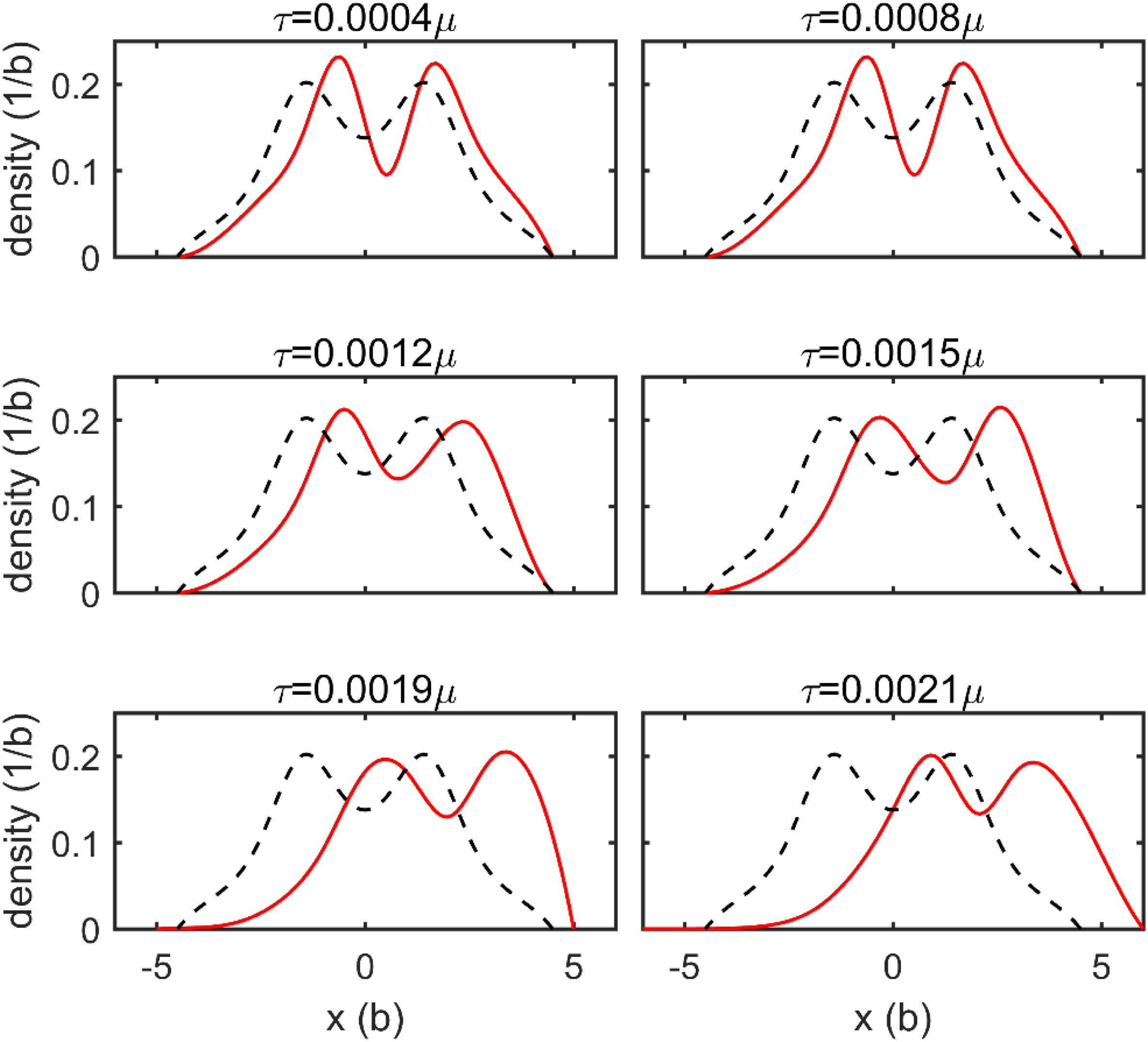
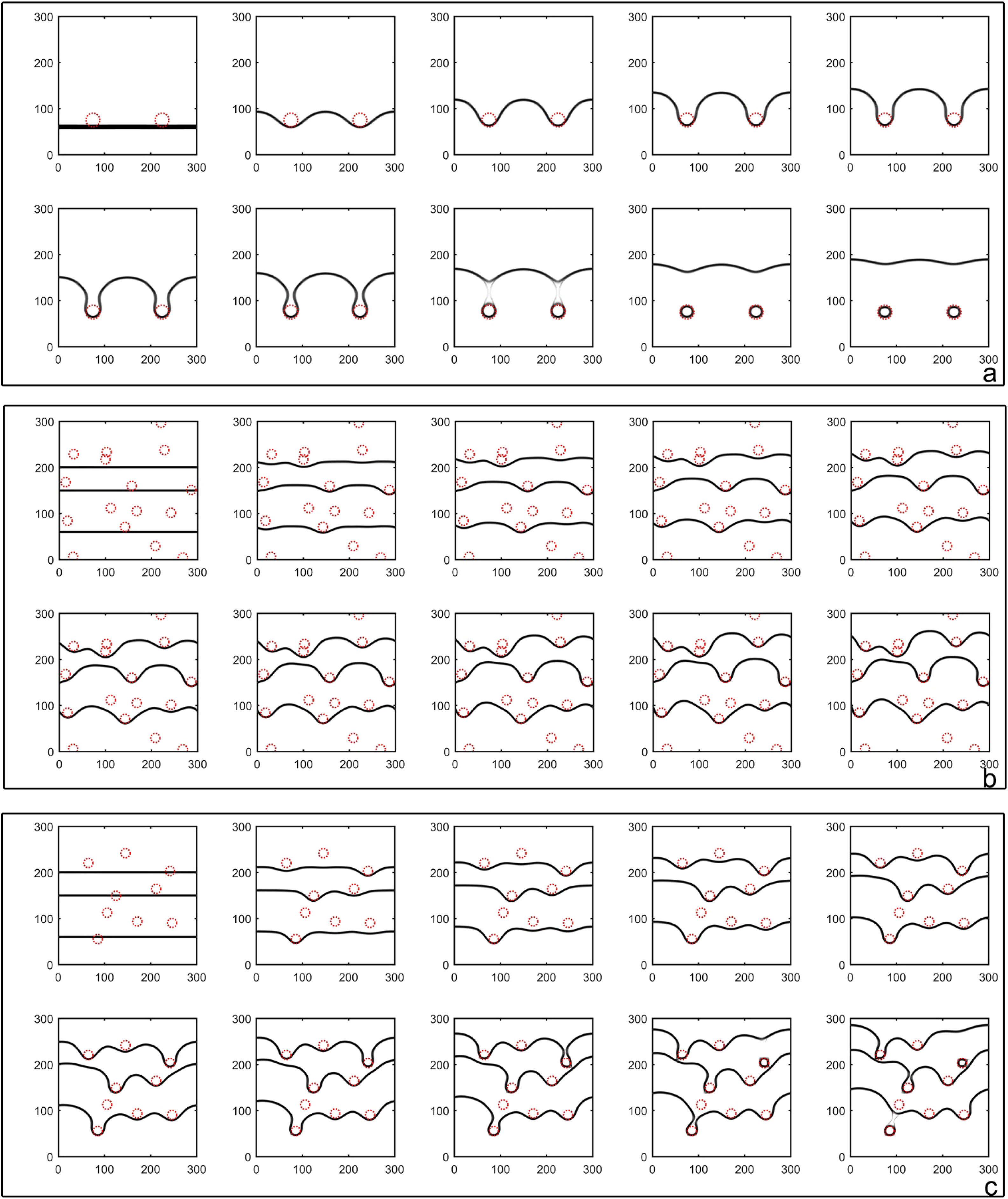
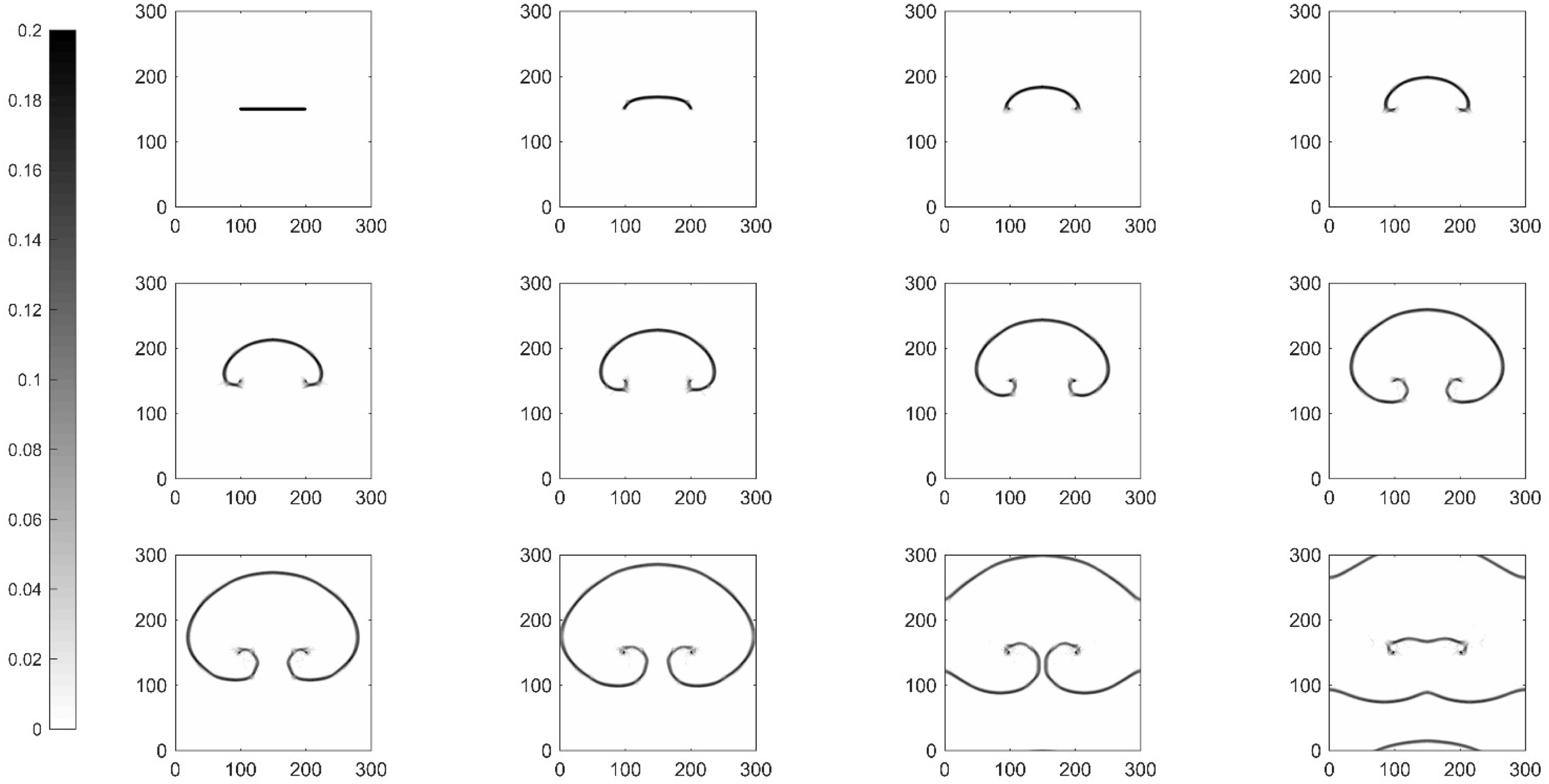
This figure shows how the proposed numerical method resolves the shape of an edge dislocation line in different stress values. The simulation shows how a straight dislocation line passes through spherical obstacles. The obstacles were in different patterns. Frank-Read source is simulated through core shielding technique.
This paper has further details:
Dislocation-density dynamics for modeling the cores and Peierls stress of curved dislocations,
Yuqi Zhang and Alfonso H.W. Ngan,
Int. J. Plast. 104, 1–22 (2018). (DOI: 10.1016/j.ijplas.2018.01.009) (abstract)
2015
Size dependence of yield strength simulated by a dislocation-density function dynamics approach
The work reported here is supported by funding from Kingboard Endowed Professorship in Materials Engineering.
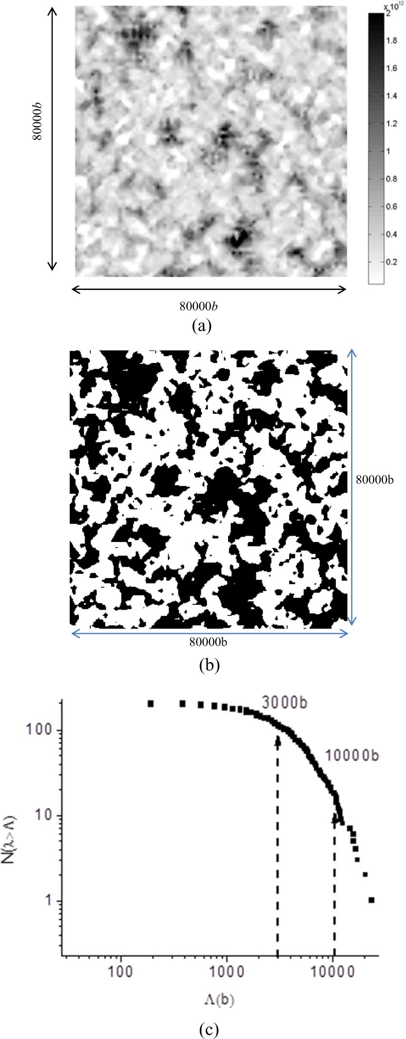
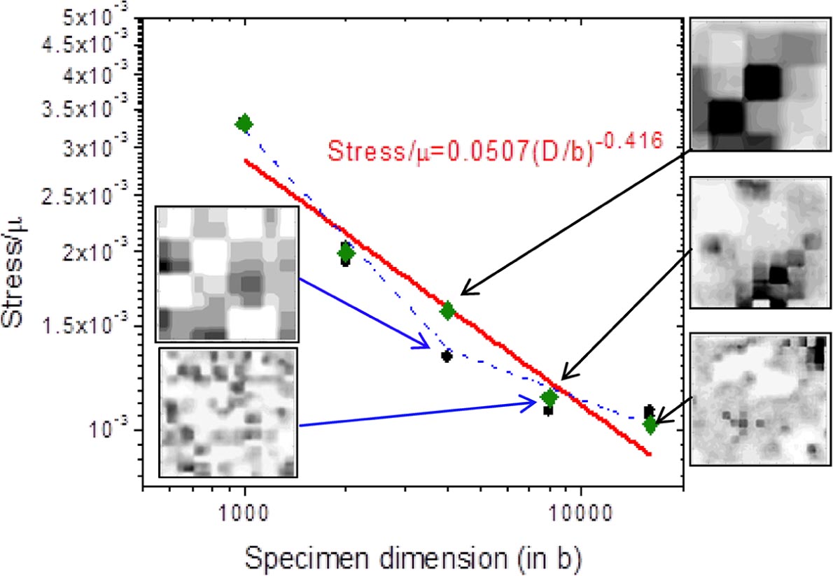
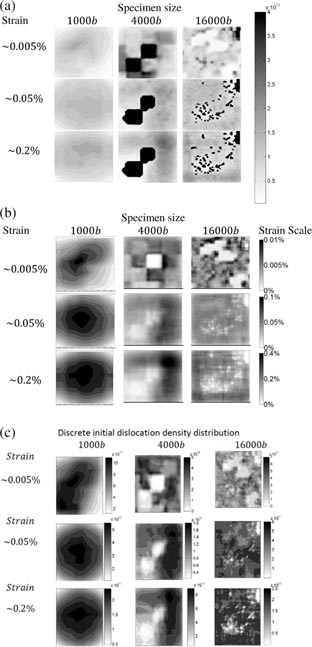
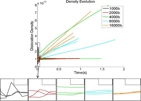
This image shows the master microstructure sample that is cropped in order to gain a realistic initial dislocation microstructure. The spatially averaged dislocation density in this simulation is 1012 m−2. This plot shows the sample size effect on plasticity, which was simulated by the DDFD method. It shows the bi-linearity in the figure of tensile strength vs. the size of a single crystal because of the dislocation density starvation mechanism in the smaller samples. Insets show the corresponding initial dislocation structures. This figure shows the resulting microstructures of different sample sizes simulated via the DDFD method. (a) shows the dislocation density maps of three distinct sample sizes, which verify the appearance of hard surface and soft core microstructures. (b) and (c) show the strain maps and the generated dislocation density during plastic deformation in three distinct sample sizes. This plot shows how the summation of dislocation density over the simulation box changes during plastic deformation of different sample sizes. Three random samples generated from the master microstructure for each specimen size were simulated.
This paper has further details:
Size dependence of yield strength simulated by a dislocation-density function dynamics approach,
P.S.S. Leung, H.S. Leung, B. Cheng, and A.H.W. Ngan,
Modelling Simul. Mater. Sci. Eng. 23, 035001 (2015). (DOI: 10.1088/0965-0393/23/3/035001) (abstract)
(New) DDFD by explicit consideration of dislocation elastic interactions
This work is supported by funding from Kingboard Endowed Professorship in Materials Engineering.
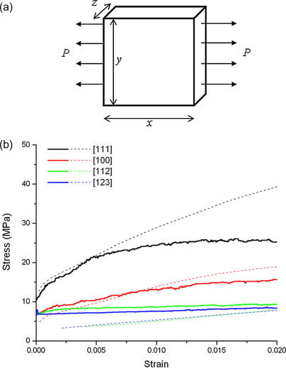
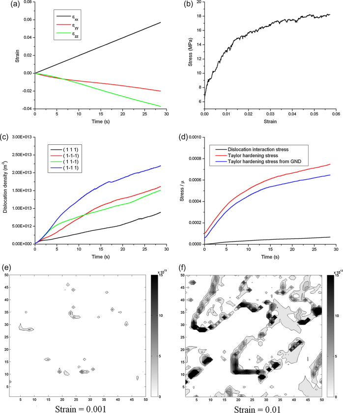
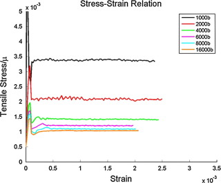
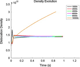
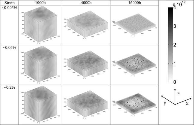
The stress-strain behavior of aluminum in a uniaxial tensile test simulated via a dislocation density function dynamics scheme. The sample is constrained in the z dimension, and dislocation lines are free to move out of the simulation box in the x and y dimensions. The stress, strain, and dislocation density changes regarding time are illustrated in figures (a–d), also the dislocation density map is illustrated in figures (e,f) after 0.001 and 0.01 of strain respectively. Stress-strain curves for different sample sizes show how the dislocation density function dynamics can resolve the sample size effect during plastic deformation. The change in summation of dislocation density inside the simulation box by time is shown in the figure for different sample sizes. Dislocation density maps in different strains show how dislocation density is distributed in different sample sizes.
This paper has further details:
A new dislocation-density-function dynamics scheme for computational crystal plasticity by explicit consideration of dislocation elastic interactions,
H.S. Leung, P.S.S. Leung, B. Cheng, and A.H.W. Ngan,
Int. J. Plast. 67, 1–25 (2015). (DOI: 10.1016/j.ijplas.2014.09.009) (abstract)